As 3GPP continues the standardization process for 5G, it is now well understood that 5G Quality of Service (QoS) will be applied purely on a per-Quality of Service Flow (QoS Flow) basis versus the previous per-Evolved Packet Service (EPS) bearer basis in 4G LTE. It is important to remember that the QoS Class Identifier (QCI), Allocation and Retention Priority (ARP), Guaranteed Bit Rate (GBR), Maximum Bit Rate (MBR), and Aggregate Maximum Bit Rate (AMBR) parameters were the five primary QoS parameters that could be determined for the EPS bearer. The operator specifies those parameters using the guidelines in the 3GPP and GSMA documents and specifications, as well as their own field experience. History shows us that this QoS implementation strategy devised by 3GPP has been very successful in the LTE networks built over the last seven to eight years, with a multitude of different types of services rolled out requiring GBR, or non-GBR QoS, with a wide range of latency requirements, i.e., VoLTE. Here, we will examine what is happening with the evolution of the QCI parameter as the industry moves forward towards 5G.
First, let’s go back and review the 3GPP definition of QCI and its characteristics. From the 3GPP Technical Specification TS23.203, Policy and Charging Control Architecture (Release 15), the following list of performance characteristics were defined for all QCIs.
- Resource Type (GBR or non-GBR)
- Priority Level (PL)
- Packet Delay Budget (PDB)
- Packet Error Loss Rate (PELR)
In addition, two more performance characteristics have been defined for some QCIs.
- Maxium Burst Size
- Data Rate Averaging Window
The QCI was defined to be a scalar value that is used as a reference by the eNodeB for the scheduling of the packets for that EPS Bearer, and each of the characteristics supplies information to the eNodeB to help it properly do that scheduling.
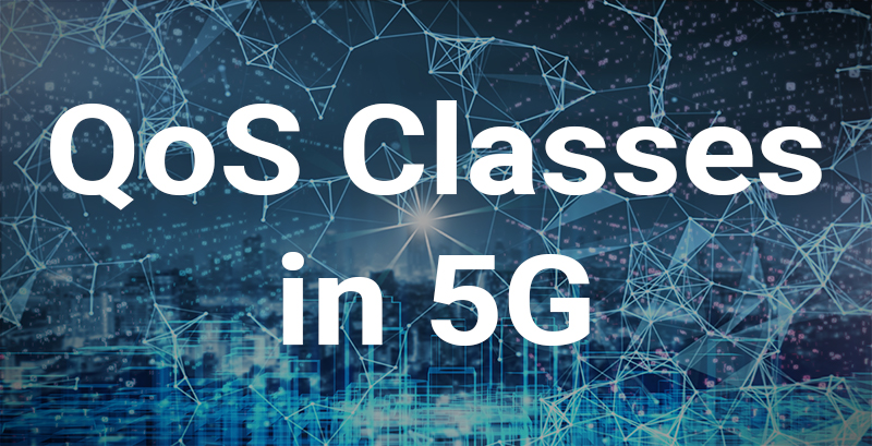
For ease of viewing, two separate tables are shown below by resource type, with Table 1 depicting GBR example services and Table 2 depicting non-GBR example services, both of these tables being derived from Table 6.1.7-A of TS23.203. Note that these tables are simplified for the sake of clarity and brevity and do not contain the complete set of associated notes from the specification.
These tables show the QCIs and associated example services, along with the first four QoS performance characteristics.
Listed below is a quick review of the four characteristics.
The resource type is self-explanatory and essentially divides the QCI types into two categories - QCIs for services requiring Guaranteed Bit Rate treatment or QCIs for services requiring Non-Guaranteed Bit Rate treatment.
The Priority Level column refers to the priority for the packets to be scheduled, with the lower priority numbers corresponding to the higher priority level.
The Packet Delay Budget column provides an upper bound for the tolerable packet delay in milliseconds between the User Equipment (UE) and the Policy and Charging Enforcement Function (PCEF), which is typically co-located with the Packet Data Network (PDN) Gateway or P-GW.
The Packet Error Loss Rate (PELR) column defines an upper bound for the tolerable loss of Service Data Units (SDUs), or in simplified speech, the payload portion of packets over the airlink between the eNodeB and the UE. According to TS 23.203 Policy and Charging Control Architecture, these are “SDUs that have been processed by the sender of a link layer protocol (e.g., RLC in E-UTRAN), but that are not successfully delivered by the corresponding receiver to the upper layer (e.g., PDCP in E-UTRAN).” In simplified terms, these are non-congestion-related packet losses intended to capture the failure of the airlink and its lower layer retransmission protocols, Radio Link Control (RLC) and Hybrid Automatic Repeat Request (HARQ), to successfully deliver transmitted packets from the transmitting end of the airlink to the receiver.
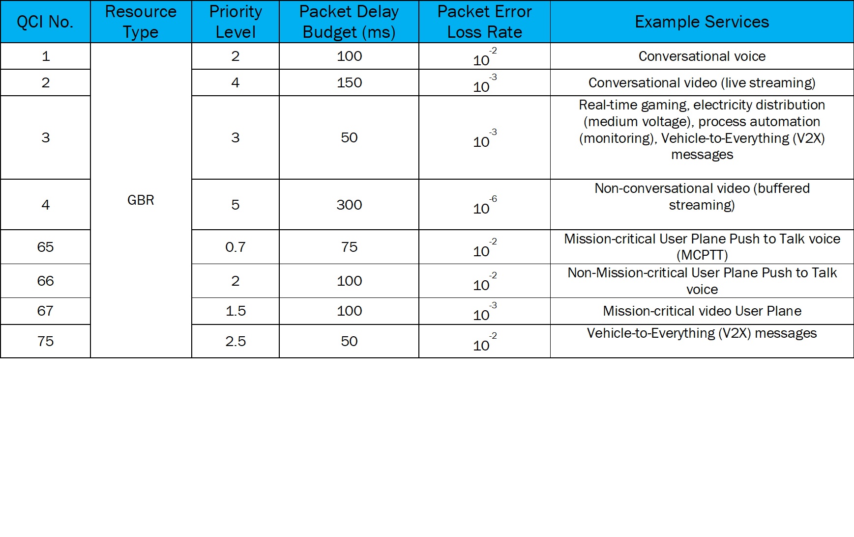
Table 1 (GBR-based Services)
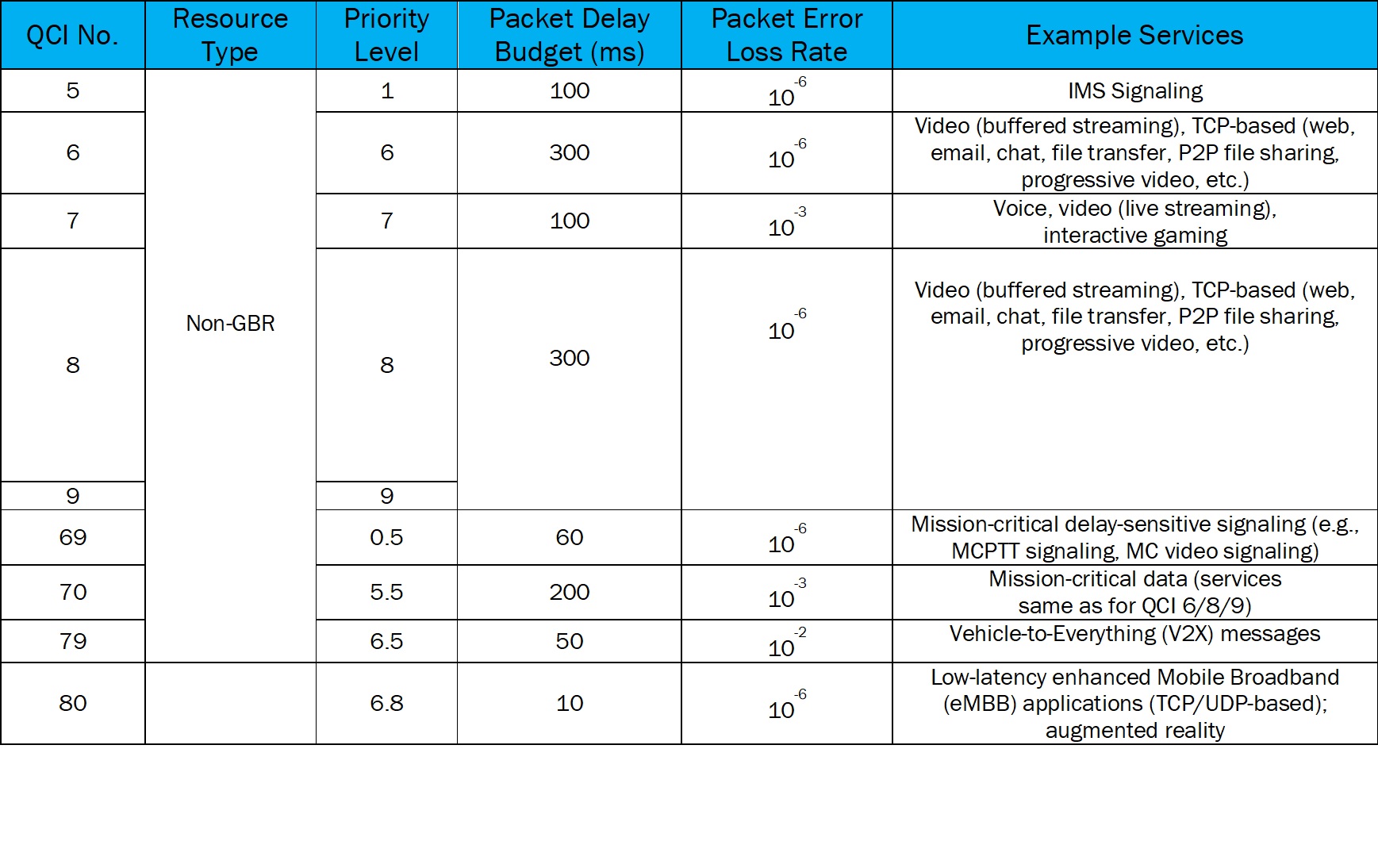

Table 2 (Non-GBR-based Services)
In addition, Table 3 below depicts additional GBR example services, along with the extra fifth and sixth performance characteristics. This table is derived from Table 6.1.7-B of TS23.203, and the newer characteristics are listed below.
The maximum burst size is the amount of data that the radio access network is expected to deliver within the packet delay budget.
The data rate averaging window refers to a sliding time window (or duration) that is used for calculating GBR and MBR values in the RAN, PDN-GW, and UE

Table 3 (Additional GBR-based Services)
At this point, there are several important takeaways that need to be summarized before proceeding to look at the corresponding 5G information. First, there has been a huge growth in the number of QCIs and example services supported for 4G LTE, since the initial release of this specification (Release 8). 3GPP has not been waiting for 5G to handle the next generation of advanced services, and the present state of the QCI parameter shows support for:
- Smart Grid (both medium and high voltage)
- Process Automation Monitoring
- Autonomous Vehicles (V2X messaging)
- Mission-critical Public Safety applications
- Low-latency enhanced Mobile Broadband (eMBB)
- Augmented Reality
- Discrete Automation
- Intelligent Transport Systems
It is interesting to look over the variance in the values of the performance characteristics for the next generation advanced services. Of particular interest are the QCI values from 80 – 85, all of which have packet delay budgets of 30 milliseconds or less (remember that this delay budget is from UE to PCEF/P-GW). Also, the next generation services supported by QCIs 82 – 85 require the additional information provided by the maximum burst size and data rate averaging window for aiding the eNodeB scheduler to provide satisfactory service.
To understand the 5G equivalent of the QCI parameter, 3GPP Technical Specification TS23.501, System Architecture for the 5G System, provides the relevant information. From section 5.7.2.1, the 5G QoS Identifier (5QI) parameter is defined, and again, it is defined to be a scalar value that is used as a reference by the eNodeB for the QoS forwarding treatment. The 5QI is equivalent to the QCI in 4G LTE. Tables 4 and 5 below show the 5QI table 5.7.4-1 in the 3GPP specification, as broken out by GBR and non-GBR example services again. In addition, Table 5.7.4-1 of the specification now breaks out a new category of 5QI, called Delay-Critical GBR, and the associated 5QIs are shown in Table 6 below.
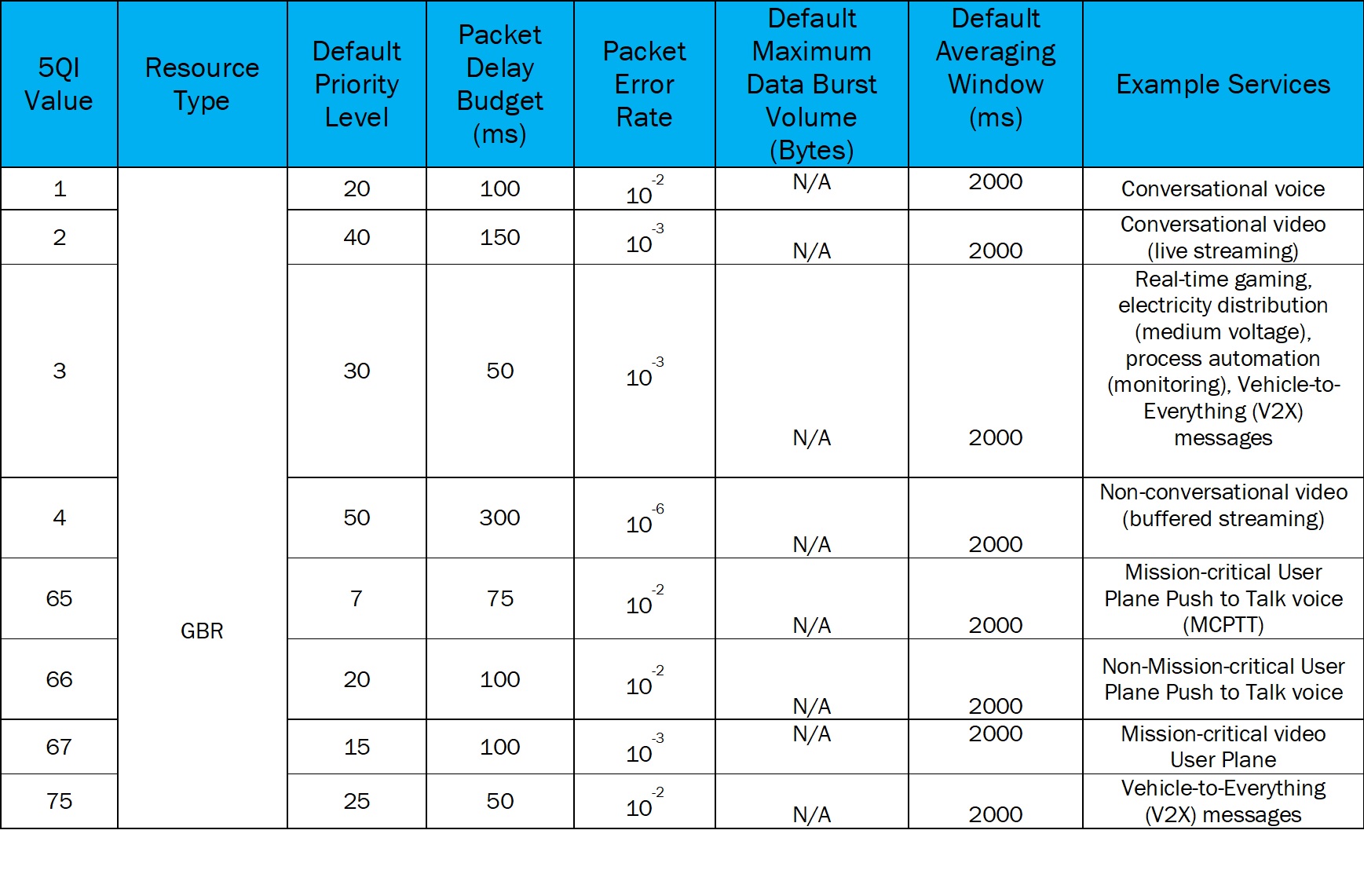

Table 4 (GBR-based Services)
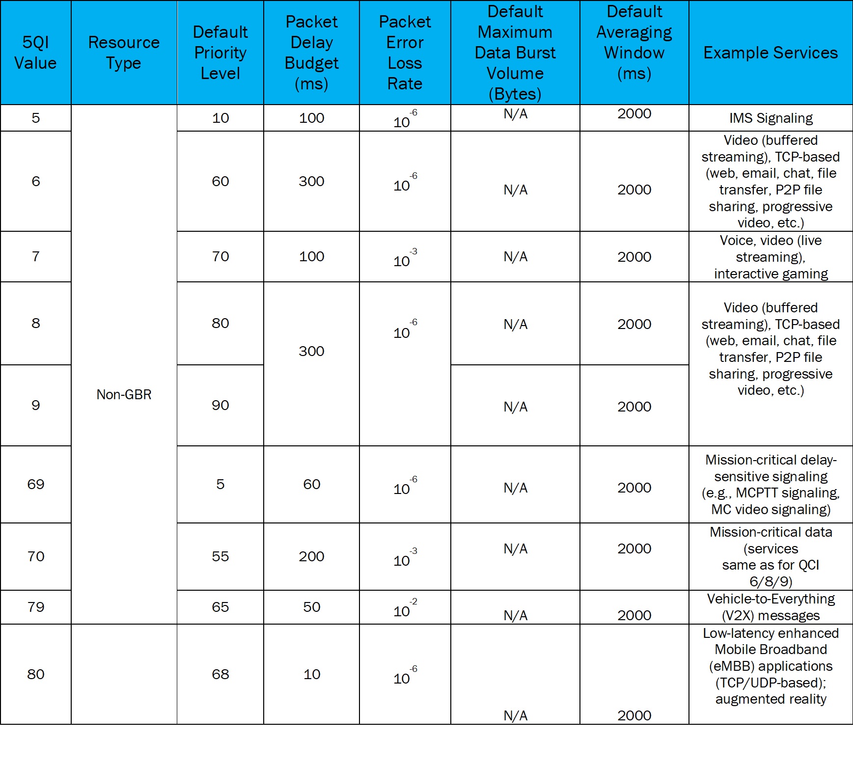

Table 5 (Non-GBR-based Services)
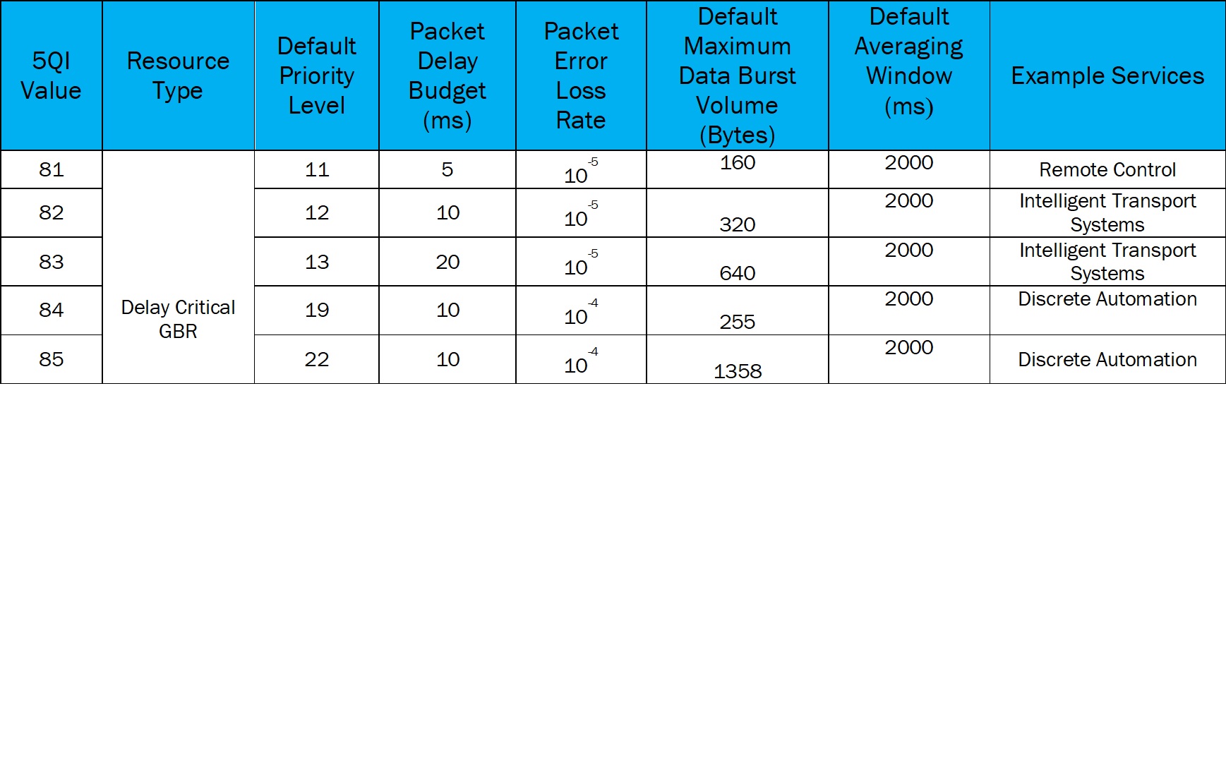

Table 6 (Delay-critical GBR-based Services)
After looking at Tables 4, 5 and 6, it can be seen that there is a lot of commonality between the 4G QCI and the 5G 5QI tables, and the 5QI tables are clearly a direct evolution of the QCI tables. From TS23.501, Section 5.7.3, 5G QoS characteristics, a high-level summary of the 5G performance characteristics is provided below, along with contrasting information versus the associated 4G characteristic.
The resource type is again mostly self-explanatory and shows some refinement versus the 4G definition. The QCI types are now divided into three categories - QCIs for services requiring GBR treatment, QCIs for services requiring Delay-Critical GBR treatment, or QCIs for services requiring Non-GBR treatment. This new Delay-Critical GBR resource type can be seen as an evolution of the additional GBR services that were called out in Table 3 above for 4G.
The Default Priority Level column evolves directly from the Priority Level column shown in Tables 1 – 3 for 4G. When examining the definitions from TS 23.501 for the 5G Default Priority Level versus TS 23.203 for the 4G Priority Level, the emphasis is on the default priority level being used as a differentiator for QoS treatment for individual QoS flows, whereas for 4G, the emphasis is on the priority level being used as a differentiator for QoS treatment for aggregations of Service Data Flows (SDFs). Again, lower priority numbers correspond to the higher priority level.
The Packet Delay Budget column evolves directly from the column of the exact same name shown in Tables 1 – 3 for 4G. This performance characteristic provides an upper bound for the tolerable packet delay in milliseconds between the User Equipment (UE) and the new 5G Virtual Network Function called the User Plane Function (UPF). Therefore, this characteristic provides almost exactly the same functionality as its 4G equivalent. The UPF is equivalent to the user plane – packet routing – functions of the 4G S-GW and P-GW.
The Packet Error Rate (PER) evolves directly from the column called Packet Error Loss Rate (PELR) in Tables 1 – 3 for 4G. The intent and usage of PER is very similar to PELR. However, the wording has slightly changed. Instead of referring to SDUs, TS 25.301 refers to Protocol Data Units (PDUs). A PDU consists of an SDU with an attached header. It can be interpreted that the newer spec refers to an entire packet, instead of the payload (SDU) of the packet that is referred to in the 4G definition of PELR. Again, in simplified terms, these are non-congestion-related packet losses, intended to capture the failure of the air link and its lower layer retransmission protocols, to successfully deliver transmitted packets from the transmitting end of the air link to the receiver.
The Default Data Maximum Data Burst Volume (MDBV) evolves directly from the column in Table 3 called Maximum Burst Size. In 5G, each delay-sensitive GBR QoS flow will be associated with an MDBV. Table 3 shows a portion of the overall 4G QCI table in TS 23.203, where 3GPP was clearly beginning to group and emphasize the most delay-sensitive GBR applications being considered by cellular network operators, and the 4G maximum burst size was a newer performance characteristic. The definitions are essentially the same for both the 4G maximum burst size and 5G data maximum data burst volume, with the 4G eNB or the 5G Access Node (5G-AN) being required to deliver up to this maximum amount of data within the packet delay budget. Note that for the GBR and non-GBR 5QIs, the default MDBV is not applicable and has no value.
The default averaging window evolves directly from the Data Rate Averaging Window column in Table 3. The definition is exactly the same for both 4G and 5G performance characteristics. In other words, it defines the sliding time window (or duration) that is used for calculating GBR and MBR values in the RAN, UPF, and UE.
As seen from the QoS performance characteristics definitions alone, a direct evolution from 4G QCI to 5G 5QI is very clear. Other major takeaways include the fact that Table 4 is essentially a direct translation of Table 1, with identical values being used for 5QI, default priority level, packet delay budget, packet error rate, and example services entries versus the 4G equivalents. The same is true when comparing Table 5 to Table 2. Default Maximum Data Burst Volume and Default Averaging Window have now been added as standard columns for Tables 4 and 5. However, MDBV is N/A in both tables, and Default Averaging Window is N/A for Non-GBR services and is set to a single value of 2000 ms for all GBR services. The 5QI values are created simply by multiplying each QCI value in Tables 1 and 2 by a factor of 10, creating exactly the new double-digit 5QI values, which is simple, elegant, and greatly expands the range of possible values for the future.
The last major takeaway involves the comparison of Table 6 versus Table 3. Table 3 for 4G had already started the double-digit values for QCI, and the values of 82 – 85 translate directly over to the 5G Table 6. A new remote-control service, 5QI of 81, has been created in Table 6, with no equivalent in Table 3, and the high-voltage electricity distribution service, 4G QCI of 85, has been replaced (thus far) with the Discrete Automation 5G 5QI of 85. Beyond this, there has been some juggling of the services and associated values for some of the additional Table 6 values.
3GPP looks to be doing a very complete job of transitioning the network end-to-end QoS scheme from 4G to 5G, as reflected in the evolution of the 4G QCI to the 5G 5QI QoS parameter.
References:
3GPP Technical Specification TS23.203, Policy and Charging Control Architecture
3GPP Technical Specification TS23.501, System Architecture for the 5G System
About Award Solutions:
Award Solutions is the trusted training partner to the world's best networks. We help companies tackle new technologies by equipping their teams with knowledge and skills. Award Solutions invests heavily in technology, research, engineering, and labs to ensure our customers make the most of their resource and network investments.
Award has expertise and training across all technologies that touch wireless: 5G, Artificial Intelligence, Data Manipulation, Automation, Machine Learning, Network Virtualization, Data Visualization, 4G LTE, and more.